Reverse Engineering A Shock Collar
I bought a random ass shock collar off of eBay. I figured if it’s already been reverse engineered, that’d be neat, and if not, I’d have a little project to get side-tracked on.
Disclaimer: Don’t use these devices on any animal, it’s cruel and probably illegal. I wouldn’t want to endorse using these on yourself either. At least read up on safety. This article is here for education only, and I can’t take responsibility for what you do with it.
Okay, so with that out of the way, here’s that little project I got side-tracked on! With the end goal of making video games hurt me, we’ll be exploring some RF stuff! Fun!
Contents
Overview
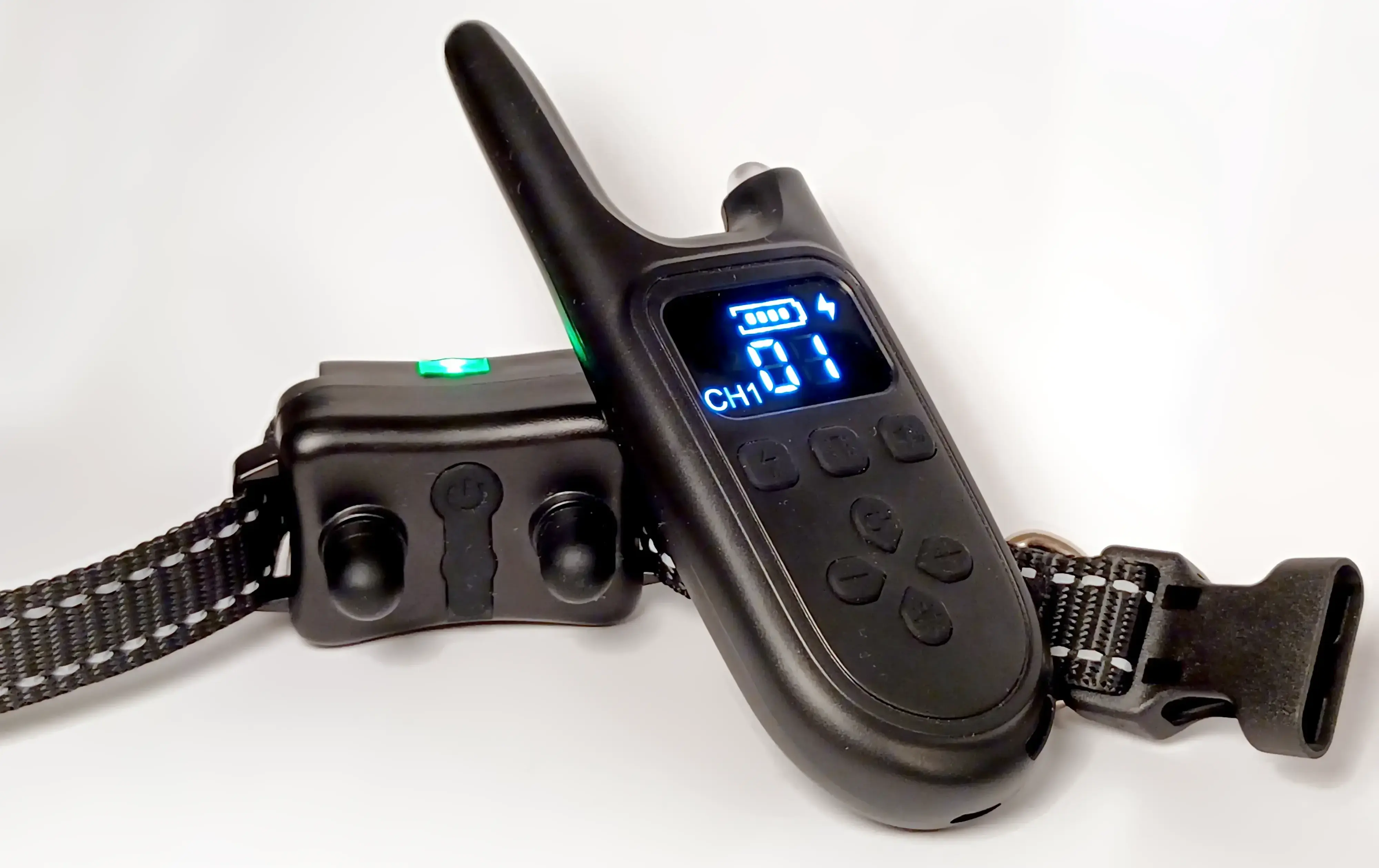
The device consists of the shocker itself as well as a remote control. There are three modes: shock, vibration, and sound. The former two can have their intensity1 adjusted from 0 to 99. There’s also a channel setting so that the remote can speak to three different devices.
When you go ahead and press a button on the remote, here’s roughly what happens:

First, the command (e.g., “shock with intensity 8 on channel 1”), gets encoded into ones and zeros. This packet gets encoded again into a digital signal, before finally being used to modulate a radio wave, yielding the RF signal.
To reverse engineer this, we’ll work our way backwards: Starting with the RF signal, we’ll decode it back into bits, and figure out how to assemble a command into the right bits. Then, it’s just a matter of sending our own commands.
Decoding the RF Signal
One neat thing about pretty much any wireless device is they need to be
tested for compliance. This means there’s likely a whole bunch of
compliance testing documentation
floating around online.
My model of shock collar had YX-2044-TX-V14 silk-screened on the
remote’s PCB.
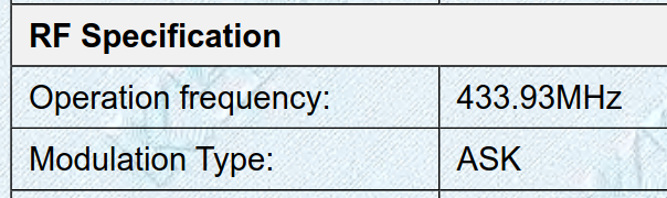
Excerpt from the device’s compliance docs.
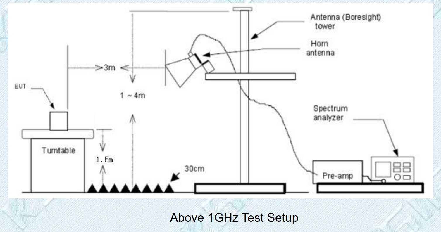
As expected (it already said so on the box2), the device operates at 433 MHz. It’s a region within the electromagnetic spectrum that wireless devices of all sorts can operate in without needing a license. Think car key fobs, garage door openers, remote-controlled power sockets, etc.
“ASK” is short for amplitude-shift keying, a way to modulate a signal onto an RF carrier frequency by means of varying the carrier’s amplitude. Kinda like AM radio, but for digital signals. This is good, since ASK is a very, very simple kind of modulation3.
Connecting Up
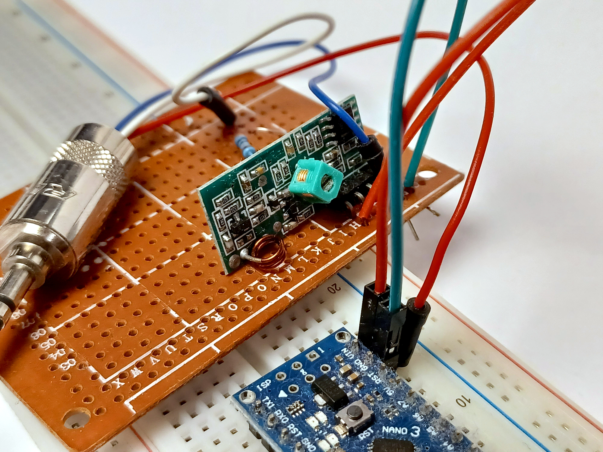
With that in mind, I ordered myself a 433 MHz transmitter/receiver pair for cheap. To capture the signal, I need to wire up the receiver, to something like an oscilloscope. I don’t have an oscilloscope, but luckily, my sound card will do just fine:
A remote like this might output data at a rate of around one bit per millisecond. That’s 1000 bits per second, which gives us ample headroom to sample the signal with any standard PC sound card, since those can do at least 44100 samples per second.
First of all, the receiver needs 5 V and GND, which I just plugged into an Arduino. I also connected the audio jack’s sleeve4 to GND.
The signal the receiver outputs is 5 volts for a 1, which will
probably be too much for the poor little sound card. First result on
Google says microphone level is
0.001 V
to
0.01 V,
and line level is around
1 V.
I used a simple voltage divider, 330 kΩ and 3.3 kΩ, to get the signal level down a bit. The attenuated signal, between the two resistors, is soldered to a 3.5 mm audio jack.
This way, the peak voltage is down to 0.05 V, which should be low enough for my PC sound card to not blow up.

Listening In
Then it’s just a matter of recording the audio with something like Audacity, making sure the level does not peek, aaaaand pressing some buttons!
Huh, those aren’t the clean ones and zeroes I’ve expected…?
I’d been suspecting my shitty breadboard, because the connections felt super loose. Aaaand I was right. Things got much better after soldering everything to perfboard.
Things were still rather noisy, for which I have only myself
my power source to blame. I was just tapping the VIN and GND on an
Arduino plugged into my PC. Unplugging my webcam from the neighboring
socket helped, but for the best results, I just powered the Arduino from
a power bank.
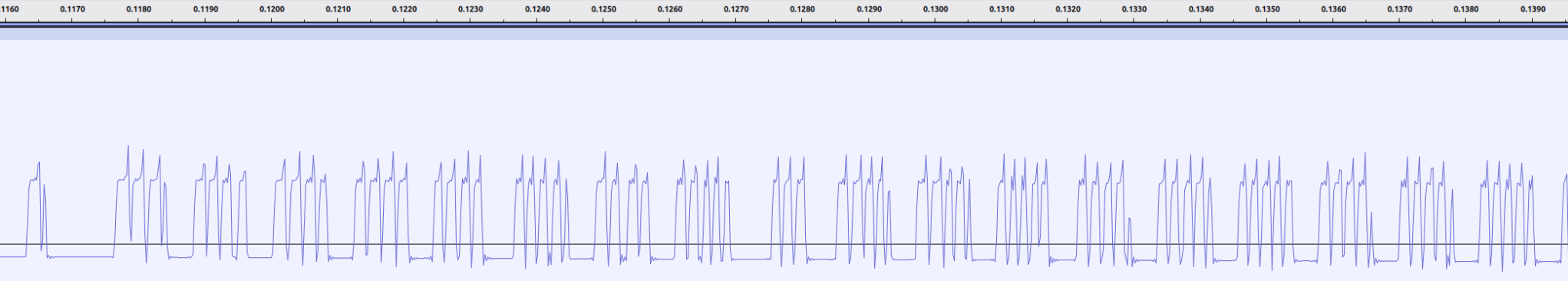
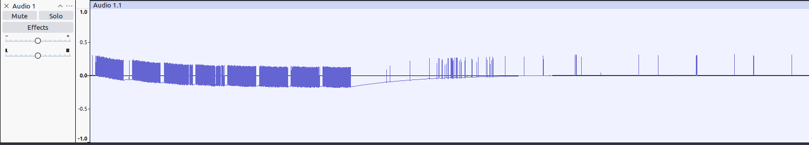
Beautiful! In the above recording, I’ve zoomed in on two button presses. We can see that each time a button is pressed, eight packets of data are transmitted. The voltage is a bit wobbly in the beginning – but turns out that’s fine.
Ok, zoom in already!
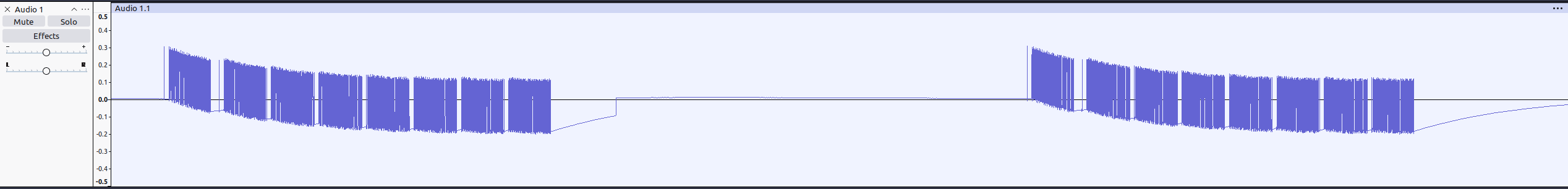
Here’s two of the individual packets. They seem to be really, really similar. They’re actually identical. Makes sense for the remote to include some redundancy this way!
Just looking at the waveform, we can see a pattern: A lot of the time, the signal is high for a long-ish duration, followed by a short pause where it’s low. At other times, there’s a fast high followed by a longer low. That smells an awful lot like bits!
| bit | pattern | image |
|---|---|---|
| 0 | long high, short low |  |
| 1 | short low, long high |  |
I’ll just go on and assume the long high, short low sequence is a zero, since I’ve seen an awful lot of those at intensity level 0, but a bit more as intensity levels increase.
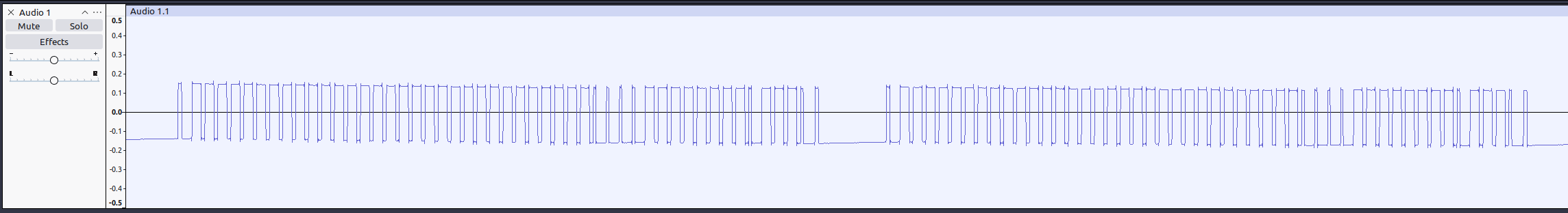
Enhance one last time!!!
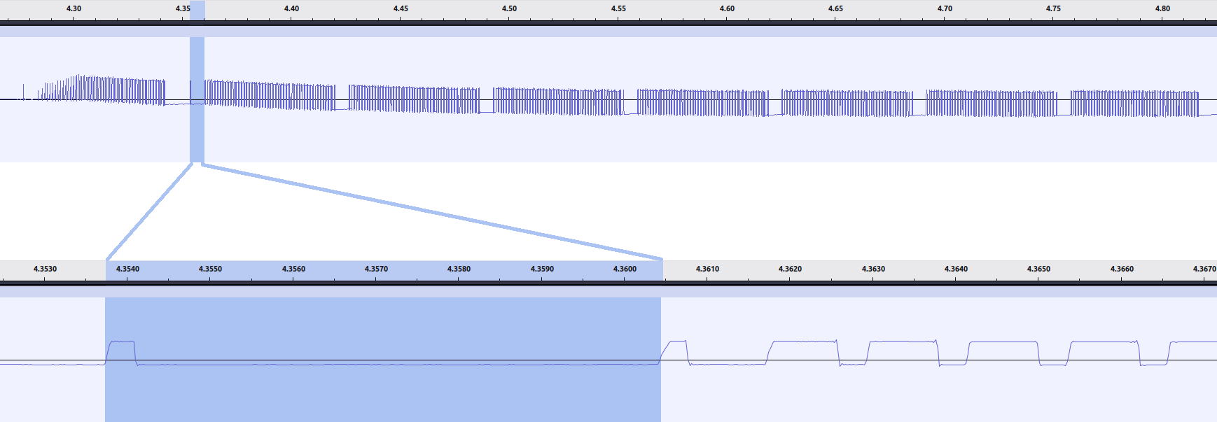
There’s one more thing worthy of note: Before the second package (ok, seems to be the same for the first one too, even tho it’s a bit too garbled to tell), we have a short high pulse followed by about 6400 µs of silence.5
Automatically Extracting Bits
To extract the bit sequences from recordings, I wrote some Python
code.
I’m a bit Pandas-illiterate, hence the deadly sin of iterating over a
DataFrame, but it works.
The idea is basically to go through the wave file and see how long each high pulse is, then either print a 1 or 0.
I also tried getting an exact number on the pulse durations by plotting
their distributions.
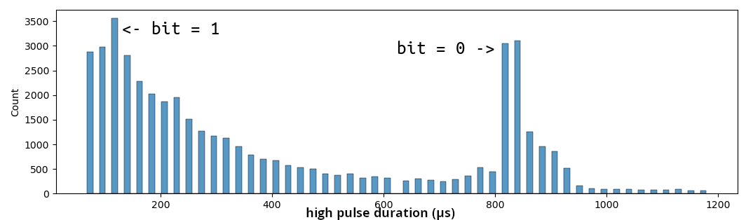
It’s a bit noisier than I’d hoped, but with some additional Audacity-eyeballing I arrived at something like 840 µs for the long pulses and 270 µs for the short ones.
Then, it’s just a matter of printing the correct bit for each high pulse and printing a newline if some amount of time has passed without any pulses.
Here’s the script running with !!headphone warning!! this recording of a shock with an intensity of 7 on channel 1:
$ ./analyze.py ../capture/shock_07.wav
00000000000


0100111001
000000000000000000110000011100001
00000000000000000000000000000001100000111000001
000000000000000000000000000000001100000111000001
000000000000000000000000000000001100000111000001
000000000000000000000000000000001100000111000001
We lose most of the first three packages, but it seems the shock at level 7 corresponds to this packet:
00000000 00000000 00000000 00000000 11000001 11000001
To get clean outputs, I did have to tweak the durations in my script.
Also, from looking at the waveform, I know there’s a 1 at the
beginning of each packet that my script missed.
Reverse Engineering the Protocol
This one’s the really fun part! It all amounts to looking at which bits change when varying any of the three input variables. Science!

Thank god for pattern recognition.
There’s three parameters you can set on the remote:
| parameter | values |
|---|---|
| mode | shock, vibrate, beep |
| channel | 1, 2, 3 |
| intensity | 0-99 for shock and vibrate; 0 for beep |
I went ahead, started a recording, and pressed a bunch of buttons: Shocks and vibrates at levels 0-10 and 99, as well as a beep for channel 1. For channels 2 and 3, I just recorded shock 99, vibrate 99, and a beep.
Here’s some extracted shocks on channel 1:
prefix                           a    b    c    d       # intensity
10000000000000000000000000000000 0000 0000 1000 0000 1  # 00
10000000000000000000000000000000 1000 0000 0100 0000 1  # 01
10000000000000000000000000000000 0100 0000 1100 0000 1  # 02
10000000000000000000000000000000 1100 0000 0010 0000 1  # 03
10000000000000000000000000000000 0010 0000 1010 0000 1  # 04
10000000000000000000000000000000 1010 0000 0110 0000 1  # 05
10000000000000000000000000000000 0110 0000 1110 0000 1  # 06
10000000000000000000000000000000 1110 0000 0001 0000 1  # 07
10000000000000000000000000000000 0001 0000 1001 0000 1  # 08
10000000000000000000000000000000 1001 0000 0101 0000 1  # 09
10000000000000000000000000000000 0101 0000 1101 0000 1  # 10
10000000000000000000000000000000 1100 0110 0010 0110 1  # 99
There’s some stuff to unpack here.
The first 32 bits of any message are always a 1 followed by 31 zeros.
We’ll get back to that later…
I’ve spaced four suspicious nibbles6 and named them a though d.
Nibble a (1/4)
Let’s start with a. It looks an awful lot like it’s
incrementing, just that the bits are backwards. Going through column
a, reading the nibble from
right to left, we have 0000, 0001, 0010, 0011, …
Yup, a is the intensity, or at least the four lowest bits.
Nibble c (2/4)
For c, reading right to left, we have 0001, 0010, 0011, 0100…
Looks like intensity plus one!
Nibble b (3/4)
The column b stays 0 for all intensity values from 0 to 10.
It does, however, change for intensity 99.
99 in binary is 0110 0011. Nibble a already encodes the right half,
0011, so b is the upper half of our intensity value – likely
reversed too.
Nibble d (4/4)
Initially, I’d gone with d and b being equal.
At this point, I’d already gone to sending commands to make sure I was on the right track (writing out of order, we’ll get there later). And turns out I was not on the right track here, since some intensity values did end up being broken.
To get d perfectly right, I had to record and look at data for some more intensity levels:
             a    b    c    d
binary:   0111 0000 1111 0000 1  # shock 14, ch 1
decimal:    14    0   15    0    # nibbles, read right to left
                 14        15    # bytes, read right to left

          1111 0000 0000 1000 1  # shock 15
            15    0    0    1
                 15        16

          0000 1000 1000 1000 1  # shock 16
             0    1    1    1
                 16        17
And yup, it’s just b plus one.
Reading ab and cd as bytes, the former encodes the intensity, the latter the intensity plus one.
Putting it all together
Finally, the message ends with a 1.
Here’s some pseudo-ish code, using reverse to reverse the four bits of
a nibble7.
const nibble reverse[] = {
  0b0000, 0b1000, 0b0100, 0b1100,    // example: reverse[0b1011]
  0b0010, 0b1010, 0b0110, 0b1110,    //        = reverse[11]
  0b0001, 0b1001, 0b0101, 0b1101,    //        = 0b1101
  0b0011, 0b1011, 0b0111, 0b1111,
};

nibble shock[] = {
  0b1000, 0, 0, 0, 0, 0, 0, 0,     // prefix (32 bits)
  reverse[intensity & 0xf],        // a
  reverse[intensity >> 4],         // b
  reverse[(intensity + 1) & 0xf],  // c
  reverse[(intensity + 1) >> 4],   // d
  0b1000                           // final `1`, don't worry about
                                   // the other three bits
};
Oops, no Device ID??
Let’s get back to that zero-laden prefix. Somewhere early on in a packet, I’d have expected to see something like the remote’s device ID or serial number, since the device’s manual mentioned something about pairing.
A pairing process would look something like this8:
- Press and hold the receiver’s (i.e., the collar’s) power button. This puts the receiver in pairing mode for a few seconds.
- Then, press any button on the remote. The remote will transmit a package, presumably with its unique serial number, as well as the channel included.
- While in pairing mode, the receiver listens for any valid package, and extracts and stores the included serial number and channel.
- From then on, the receiver will simply ignore any packets with a serial number or channel that doesn’t match.
It’s just that the serial number part is actually all zeros.

Oops!
That’s kind of a bit of an oversight by the manufacturer. It means any remote will trigger any collar, given they’re on the same one of the three channels.
I suspect the collar might have the pairing process implemented correctly, but they just didn’t bother to set a serial number for the remote. If that is the case, once I have my Arduino up and sending commands, I might be able to set a serial number myself and pair the collar to my Arduino!
Figuring out the Rest of the Protocol
Moving on with some more recordings, I was able
to figure out how the mode and channel are encoded. The most
interesting part here are the last eight bits before the final 1:
They mangle together all three parameters, thereby acting as a kind of
checksum.
| start | bits | what |
|---|---|---|
| 0 | 24 | prefix |
| 24 | 4 | mode |
| 28 | 4 | channel |
| 32 | 8 | intensity |
| 40 | 8 | checksum |
| 48 | 1 | final 1 |
For example, vibration at level 99, on channel 2:

Keep in mind to read mode, channel, and intensity from right to left.
Two new nibbles have appeared:
mode and channel – not that hard to figure out which is which, of
course.
Figuring everything out took some trial and error, the process of which I made a bit nicer with some unit tests.
The full payload, including the checksum, is generated like this:
typedef enum { SHOCK, BEEP, VIBRATE } Mode;

char buf[13];

int i = 0;
buf[i++] = 0b1000;
for (; i <= 5; ++i) {
  buf[i] = 0;
}

buf[i++] = reverse[mode];

buf[i++] = reverse[channel - 1];

buf[i++] = reverse[intensity & 0xf];
buf[i++] = reverse[intensity >> 4];

// checksum
int j = mode + 1;
buf[i++] = reverse[(intensity + j) & 0xf];
buf[i++] = reverse[((intensity + j) >> 4) + (channel - 1)];

buf[i++] = 0b1000;
Sending My Own Commands
Have another circuit drawing. Just like the last one, but with two fewer (a whole 100% decrease!) passive components:

On the software side, we take in a char*, which we’ll treat as a
nibble* for simplicity, and go through it bit by bit:
#define PACKET_LENGTH 49  // bits
#define PACKET_COUNT 8    // packet is sent this many times
#define PULSE_SHORT 300   // microseconds
#define PULSE_LONG 900    // microseconds

void send_payload(char* buf) {
  for (int n = 0; n < PACKET_COUNT; ++ n) {

    // first pulse followed by long-ish wait
    digitalWrite(OUTPUT_PIN, HIGH);
    delayMicroseconds(PULSE_SHORT);
    digitalWrite(OUTPUT_PIN, LOW);
    delayMicroseconds(6400);

    for (int i = 0; i < PACKET_LENGTH; ++i) {

      bool bit = (buf[i / 4] & 1 << (3 - (i % 4))) > 0;

      float high_time = bit ? PULSE_SHORT : PULSE_LONG;
      float low_time = bit ? PULSE_LONG : PULSE_SHORT;

      digitalWrite(2, HIGH);
      delayMicroseconds(high_time);
      digitalWrite(2, LOW);
      delayMicroseconds(low_time);
    }
    delayMicroseconds(12000);
  }
}
Using delay in between digitalWrite, may not be a thousand percent
exact, but it works perfectly fine and doesn’t overcomplicate things.
Neat and pretty straightforward with the encoding figured out.
In reality, I started wiring up the sending pretty early, at first just
replaying known messages before writing, bugfixing, and finally finishing
the set_payload function.
Wrapping Things Up
To finish everything up, I swapped the Arduino for an ESP32 to add WiFi, and literally wrapped things up in electrical tape.
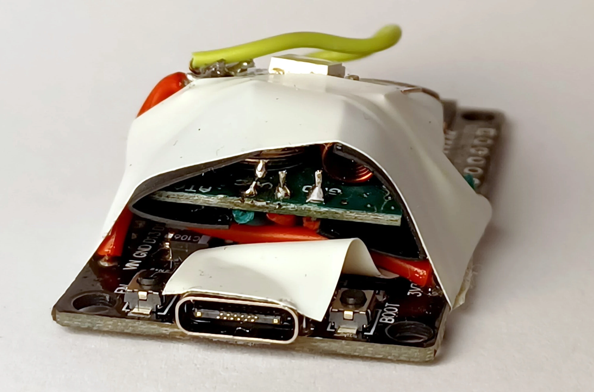
Compact and not at all sketchy-looking.
On the ESP, I installed a modified version of the OpenShock firmware – my modification being added support for this particular shocker.
I also just had to strap on an RGB LED, for extra gaming.
The firmware connects to a pretty sophisticated backend, complete with an API that people have used to create mods for various games. So I can make video games inflict pain, yay!
Anyways, it’s been a super fun little project, and I was surprised to be able to finish this in just a few afternoons.
🐾 Footnotes:
-
What does the intensity actually control? Here’s the voltage and AC frequency plotted across the range of intensity levels:
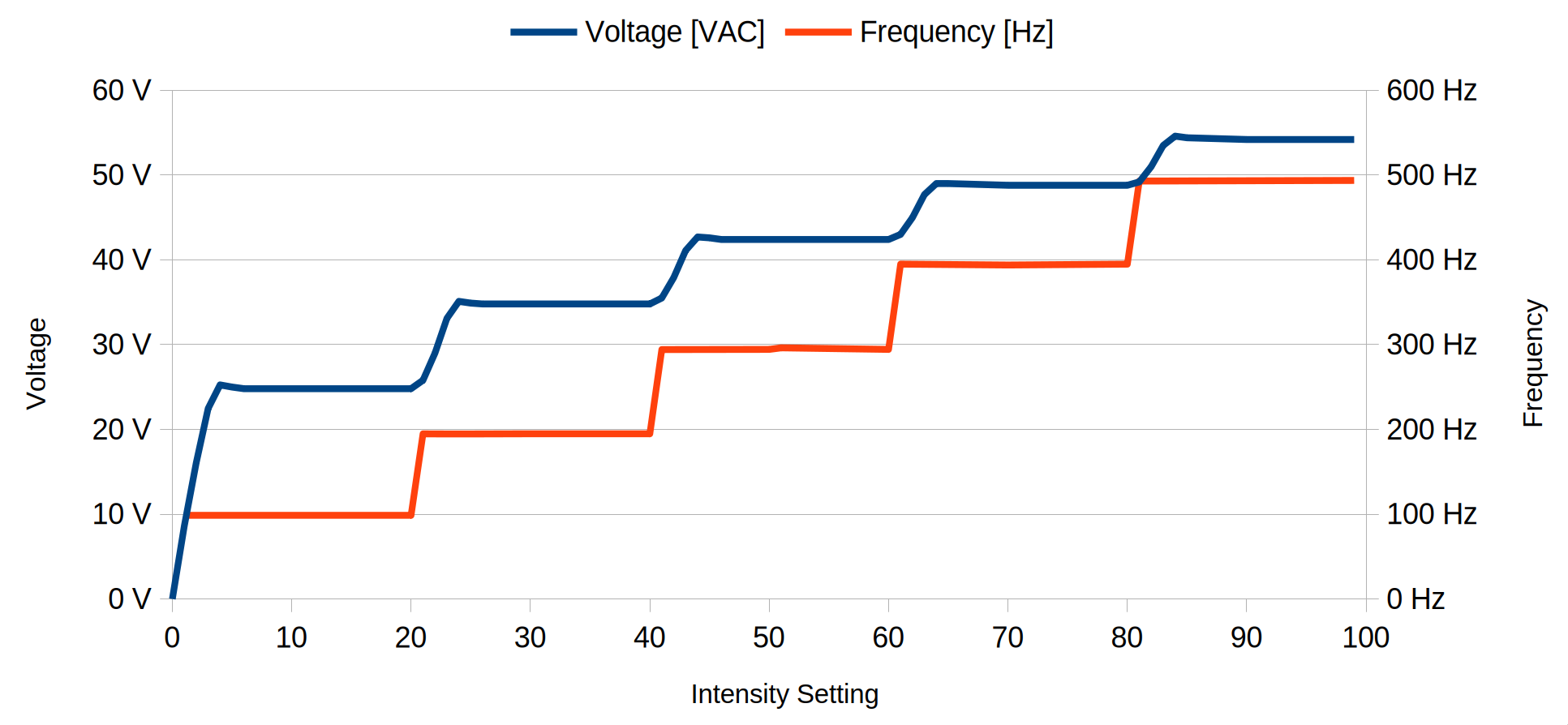 This is just measured with a simple multimeter, there may be stuff
I’m not seeing here. I’m pretty sure level 15, for example, feels
more intense than level 5. Chances are the shocker output is
pulse-width-modulated, with the duty cycle increasing as levels go
up – kinda like how an LED dimmer works. ↩
This is just measured with a simple multimeter, there may be stuff
I’m not seeing here. I’m pretty sure level 15, for example, feels
more intense than level 5. Chances are the shocker output is
pulse-width-modulated, with the duty cycle increasing as levels go
up – kinda like how an LED dimmer works. ↩ -
I guess I could’ve skipped reading the test report. But it was a fun
readskim-through. Turns out a lot of testing work goes into the process! And yet I’ve never really spared a thought to how that’s the case for anything with RF. Also, the report features some intensely passionate graphic design. ↩ -
I think modulation types are a nice Wikipedia rabbit hole. Turns out a more complex modulation, QAM, is used for both Wi-Fi and analog TV! ↩
-
The three connective bits on a stereo audio jack are named tip, ring, and sleeve; hence the jack is also referred to as TRS. Remember: The Ring is typically the Right audio channel and often connected with a Red wire. Beautiful! ↩
-
To get accurate timings from Audacity, change the unit to samples down in the Selection section, then do mathhh.
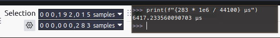 ↩
↩ -
While we’re at it, I’d like to take a moment to appreciate how cute the word nibble is :3 ↩
-
Helpful Python one-liner to generate the lookup table:
print(f'const char reverse[] = {{\n{" " + "".join(["0b" + format(i, "#06b").replace("0b", "")[::-1] + (", \n " if (i + 1) % 4 == 0 else ", ") for i in range(16)])}\n}};')↩ -
Might just be me, but it’s pretty clever how there’s no need for the receiver to talk back to the remote! Intuitively, I’d have assumed the pairing process involves some kind of negotiation between the two devices. ↩